Single Point Cutting Tool
Introduction
In our project, we conducted a comprehensive analysis of chip morphology and surface finish by manipulating top/back rake angles and cutting variables using CAD and ANSYS software. Our aim was to investigate the impact of different parameters on surface finishing, production time, energy loss, and cutting tool wear during the machining process. One of the key factors we focused on was the back rake angle, which proved to have a significant influence on the tool's finish. By employing CAD software, we were able to design and visualize the workpiece and cutting tool geometry. The ANSYS software facilitated simulations and analysis of chip morphology and surface finish, allowing us to observe the effects of varying top/back rake angles and cutting variables. To ensure improved surface finish, reduced production time, and minimized energy losses, the selection of tool geometry and cutting tool materials played a crucial role. Moreover, regular resharpening of the cutting tool was necessary to maintain its tool life and geometry. Throughout our experiments, we utilized a mild steel workpiece and a High-Speed Steel (HSS) M7 (S400) cutting tool. Our analysis provided valuable insights into the relationship between the examined parameters and chip morphology as well as surface finish. These findings will prove instrumental in optimizing the machining process, attaining superior surface quality, reducing production time, minimizing energy losses, and prolonging the tool's lifespan.
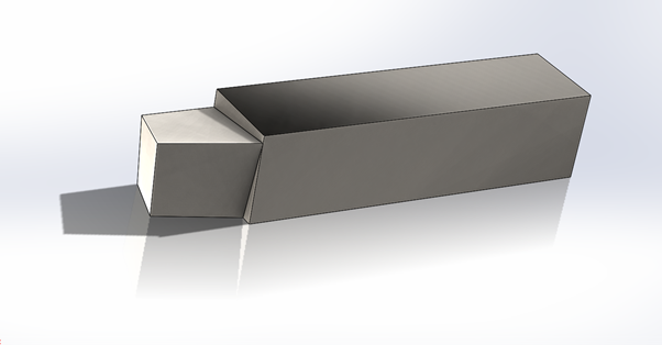
fig:- Single point cutting tool
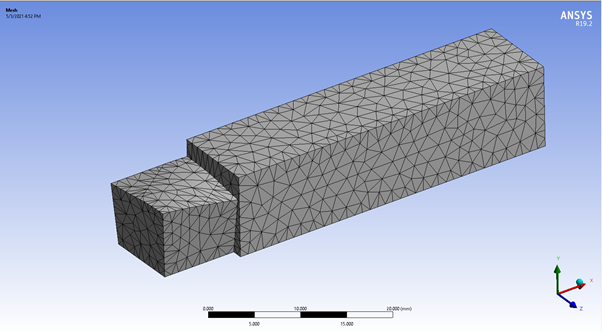
fig:- Meshing of tool
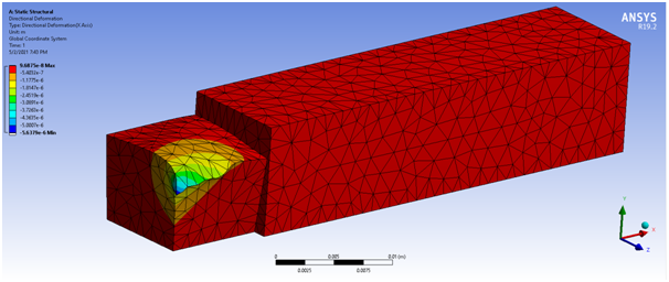
fig:- Deformation for negative rake angle
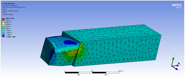
fig:- Deformation for postive rake angle
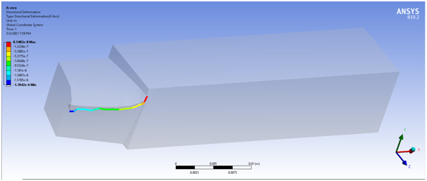
fig:- Deformation for zero rake angle
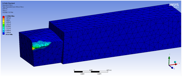
fig:- Stress for negative back rake angle

fig:- Stress for positive back rake angle
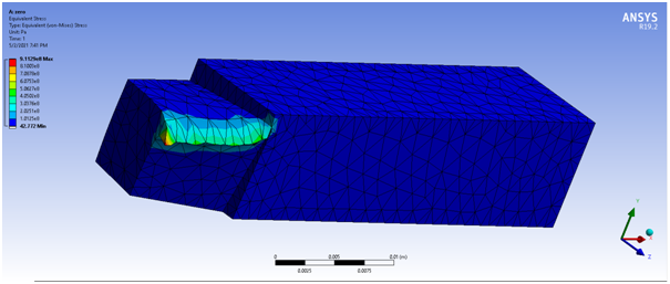
fig:- Stress for zero back rake angle
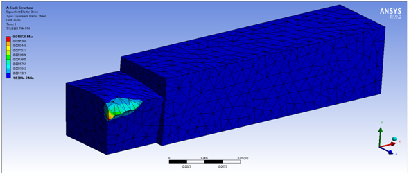
fig:- Strain for negative back rake angle
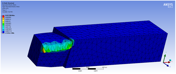
fig:- Strain for positive back rake angle
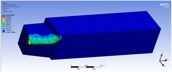
fig:- Strain for zero back rake angle
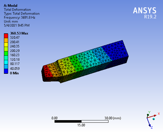
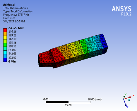
fig:- Modal analysis (Total deformation)
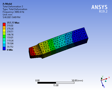
fig:- Modal analysis (Total deformation 3)
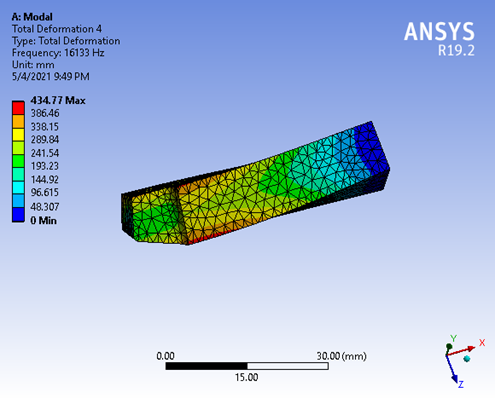
fig:- Modal analysis (Total deformation 4)
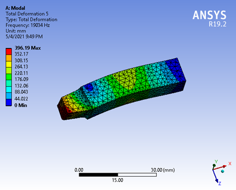
fig:- Modal analysis (Total deformation 5)
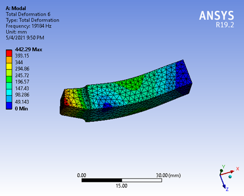
fig:- Modal analysis (Total deformation 6)